WASTE PYROLYSIS
- WASTE PYROLYSIS
TECHNOLOGY
Continuous Pyrolysis represents the thermal degradation of materials at high temperatures within an inert atmosphere. This is the most advanced and proven technology to convert any combustible material in an oxygen free atmosphere to useful products such as Oil, Carbon and Gas without any pollution.
Major advantage in Continuous Pyrolysis technology is the output Gas which can be converted to Electricity by Powering a Generator or a Turbine.
There are Two Types of Pyrolysis processes:
- Batch Process
- Continuous Process
There are many issues in Batch process such as Pollution and operational Risk also poor quality of Carbon and Oil but with less Investment. In fact this process is banned by CPCB in few States in India.
We use Safe Continuous Process Fast Pyrolysis to get Quality Products which has good market demand but the plant cost is expensive. The pollution is minimal and far less than the permitted limits by the Pollution Control Board.
Municipal Solid Wastes are categorized into Biodegradable waste and Non-Biodegradable waste.
PROCESS FLOW DIAGRAM
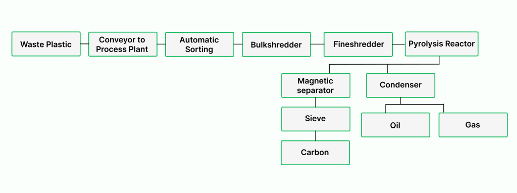
Application of the process in the Plant
- Segregated Waste Plastic is fed into the Reactor Vessel and heated under controlled conditions of temperature and pressure.
- As a result, carbonized powder is produced along with oil and other gases.
- The vaporized gases are passed through Heat Exchangers (condensed), after cooling, resulting in some quantities of Pyrolysis oil generation.
- Carbon is generated in powder form. It is further pelletized to obtain a product with high calorific value which finds market as a heating medium in industrial furnaces & as a substitute to currently available fuel inputs.
The gases produced during the process which cannot be condensed are reused to generate electricity for the entire factory, including office and machinery, making it a self-sustaining manufacturing unit on the power front.
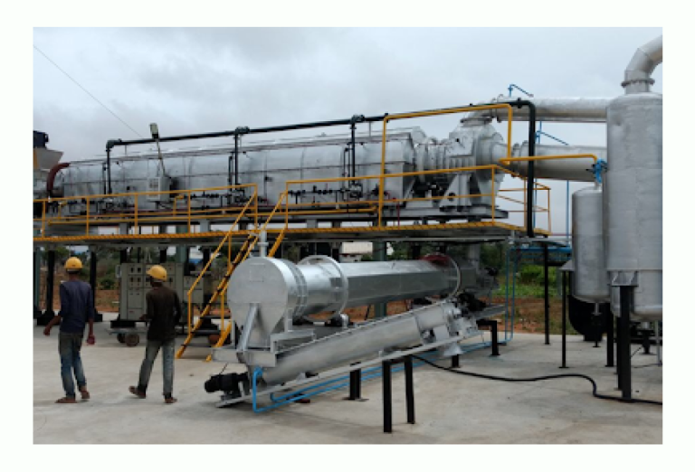
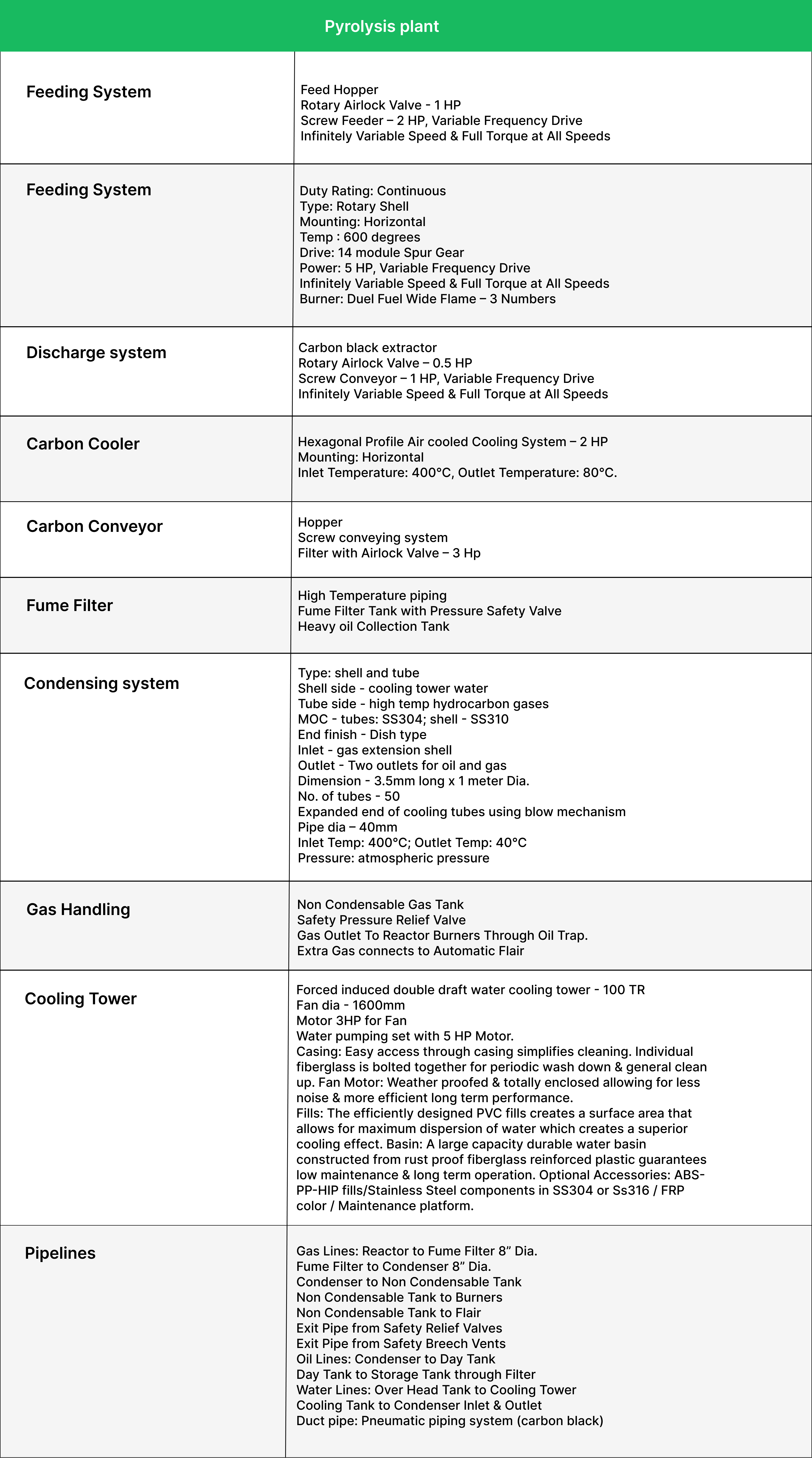
Detailed Technical Specification for Rotary Shell Pyrolysis Reactor
1. Facility description
The system is designed for the thermal decomposition of hydrocarbon materials andallows the recycling of the produced fractions, under very economic issues. The starting material is crushed and with a filling system carried in the receiving hopper and from there continuously fed to the rotary shell.
In the rotary shell, the material is heated up to 700 ° C and split into gas and solids. In the discharge casing of the rotary tube, the solids are separated from the gas. The solids are discharged with a screw conveyor from the oven and cooled to about 60 °C.
The gas is discharged from the upper part of the discharge casing and passes through
a gas cooler and condenser to condense to pyrolysis oil. The condensed oil is pumped into a day tank. The non-condensable portion of the gas is compressed to about 100 mbar and fed to the burners of the combustion chamber in order to produce the process heat to heat the rotary tube.
The non-condensable gas what is not more usable gets burned for security by using a torch, thus pre-emptively to prevent uncontrolled combustion. The plant is designed for continuous 24/7 operating with minimum 7,500 hours an year. The plant is working fully automatically.
Pollution Control Measures
- All combustible materials are converted into Oil, Carbon Pellets and Fuel Gas without any residue.
- Waste materials not subject for direct firing, only the outer shell of reactor is heated, while recycling the process gas used in Burners @ 1200 Deg. Flame temperature will get cleared of toxic chemicals.
- The flue gas from burner may contain carbon molecules so we have added the wet scrubber along flue gas line prior to Chimney Stack to control the Air pollution.
- The water used in the wet scrubber pass through sedimentation tank and fabric filter to collect carbon particles the balance water after evaporation loss is recycled for cooling tower.
- The carbon particles collected in filter will be used again as raw material along with waste plastic to eliminate the water pollution.
Methodology for Project Operations
Feed requirement
Quantity required per Day = 25 Tons for 25 days per month.
Moisture Content = Less than 20% otherwise we need more space near plant to construct the poly roofing for solar drying.
Impurities = Waste should be free of Construction debris.
The feed rate which can be processed in the reactor may vary due to Density of waste material and moisture content which have capacity to feed maximum of 30 tons per day and minimum of 20 tons per day.
Any type plastics our reactor can accept, since two special shredders one Bulk shredder and one fine shredder can bring the material to the required size for the reactor feeding.
The Least Expected Product Output:
Pyrolysis Oil (Furnace Oil) : 30%
Carbon Black : 50%
Non Condensable gas : 20%
Storage & Transportation Plan:
The Produced Pyrolysis oil shall be stored in a 10,000 litre Day tank then once in a day transferred to Bulk storage tank with capacity of 40,000 litres.
Pumping provision for Oil with metering shall be provided to load the bulkers for sale.
The carbon black bagging machine fills every 20 Kg in bags and stacked on pallets, which can be loaded into Trucks using Front End Loader.
The Gas shall be used for captive consumption of burner heating and power generation and the excessive power thus generated shall be transformed to the grid
Any non-utilized gas will be flared to prevent Air Pollution.
Process of Pelletizing Carbonized powder in Carbon Pellets:
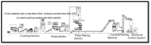
Schematic diagram of the process for manufacturing of Carbon Pellets
- Mixing of Carbon mass with the binder
Due to the different characteristics of various raw materials, the carbon mass pellet quality is inconsistent. To improve the pellet quality or maximize the production capacity, we add a binder (a kind of glue, e.g., vegetable oil or rapeseed cake) to help the lignin-lacked material to compress into pellets.
- Pellet compression process
Pellets are formed using special dies, in a pellet mill. High pressures (45,000 PSI) and temperatures (200 ºF) are generated in this process, which softens components and binds the material in the pellet together.
- Cooling of final pellets to room temperature
The fresh final pellets are very hot with extra moisture which needs to be released. The unreleased heat and moisture usually makes the pellets soft, so hence their shape is not formed. To reach the quality requirements on surface hardness and moisture content, the cooling process becomes an important part and therefore a counter-flow cooler is adopted.
- Screening of cooled pellets
To remove the fines or dust from the materials that failed in compression process and from some broken pellets, a vibrating screen is employed to get a uniform output.
- Packing and storage of screened pellets
As Carbon Pellets will not enter into the fuel process immediately, in order to keep the pellets as dry as possible and to avoid influence from water or dampness, the packing process is necessary. A pellet packing machine is used for packing the carbon pellets in 20 kg packets.
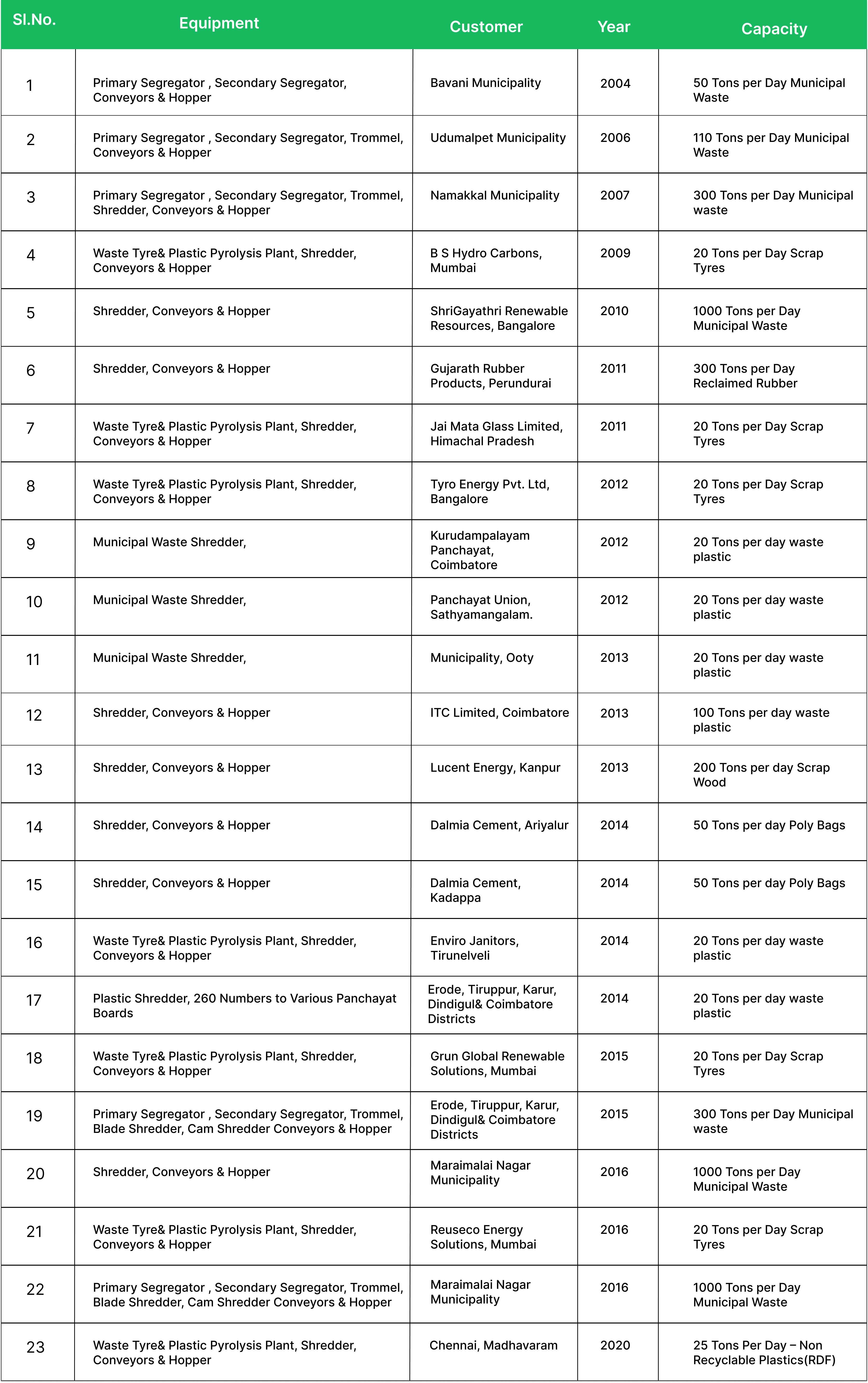
Our Experience in Waste Management - Projects Designed, Manufactured & Installed